Install and Configure VMware Site Recovery Manager 8.3 Virtual Appliance
This guide we will go over how to install and configure VMware Site Recovery Manager 8.3 Virtual Appliance on vSphere 7.0. In a future post, I will be going over how to install and configure vSphere Replication 8.3 appliance, as I feel this deserves its own blog post.
The guide will walk you through the following:
- Deploy Site Recovery Manager 8.3 Virtual Appliance
- Configure SRM Virtual Appliance
- Connect to vCenter Server
- New Site Pair
- Installing Storage Replication Adapter (SRA)
- Configure Array Pair
- Configure Inventory Mappings
- Network Mappings
- Adding IP Customization to Existing Network Mapping
- Adding IP Customization at the Protected site Network Mapping
- Adding IP Customization at the Recovery Site
- Folder Mappings
- Resource Mappings
- Placeholder Datastores
- Network Mappings
- Creating Protection Group and Recovery Plan
- Configure Recovery Plan
- Virtual Machine Recovery Settings
- Test a Recovery Plan
- Run a Recovery Plan
Lets get started!
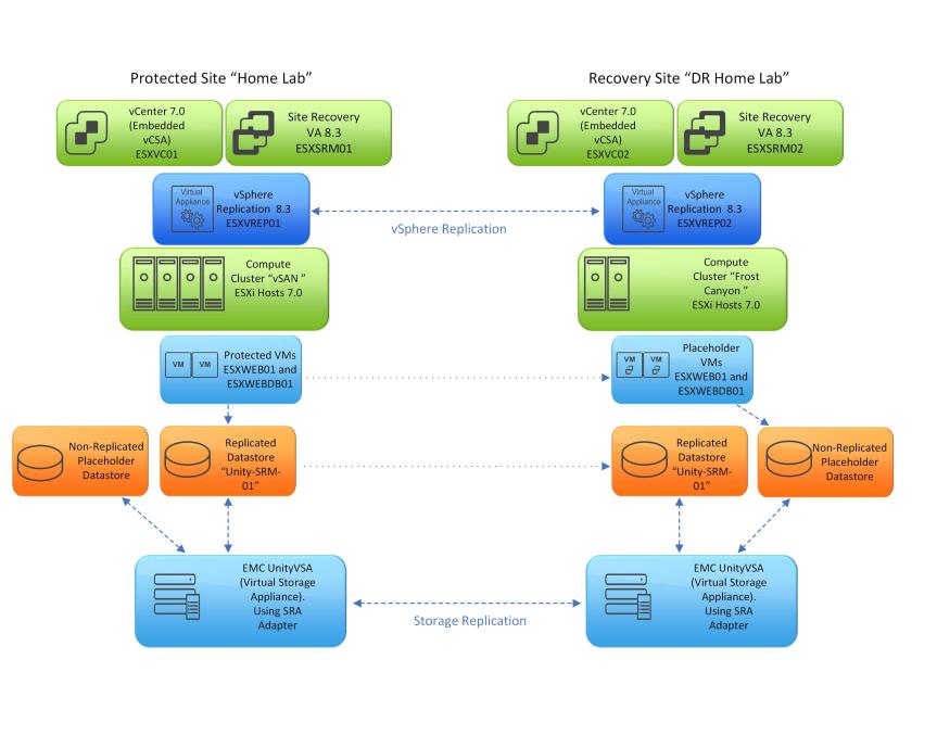
Lab Overview
Before we begin, I have already installed and configured Site Recovery Manager 8.3 at the “Protected site”. I will be using the “Recovery Site” for most of my examples in this walkthrough. I also have EMC UnityVSA deployed at both sites. The UnityVSA will be hosting replicated datastore called “Unity-SRM-01”.
Protect Site Overview
- vCenter 7.0
- AD/DNS
- Site Recovery Manager Virtual Appliance 8.3
- vSphere Replication Appliance 8.3
- EMC UnityVSA (Replicating with the Recovery Site UnityVSA)
- The Datastore “Unity-SRM-01” LUN will be created on the UnityVSA. Connected to the ESXi via iSCSI and replicated to the Recovery Site UnityVSA.
- 4xESXi hosts
- ESXi 7.0
- Intel Hades Canyon NUCs
Recovery Site Overview
- vCenter 7.0
- AD/DNS
- Site Recovery Manager Virtual Appliance 8.3
- vSphere Replication Appliance 8.3
- EMC UnityVSA (Replicating with the Protected Site UnityVSA)
- Replicated Datastore “Unity-SRM-01” will be mounted when running the recovery plan.
- 2xESXi hosts
- ESXi 7.0
- Intel Frost Canyon NUCs
Deploy Site Recovery Manager 8.3 Virtual Appliance
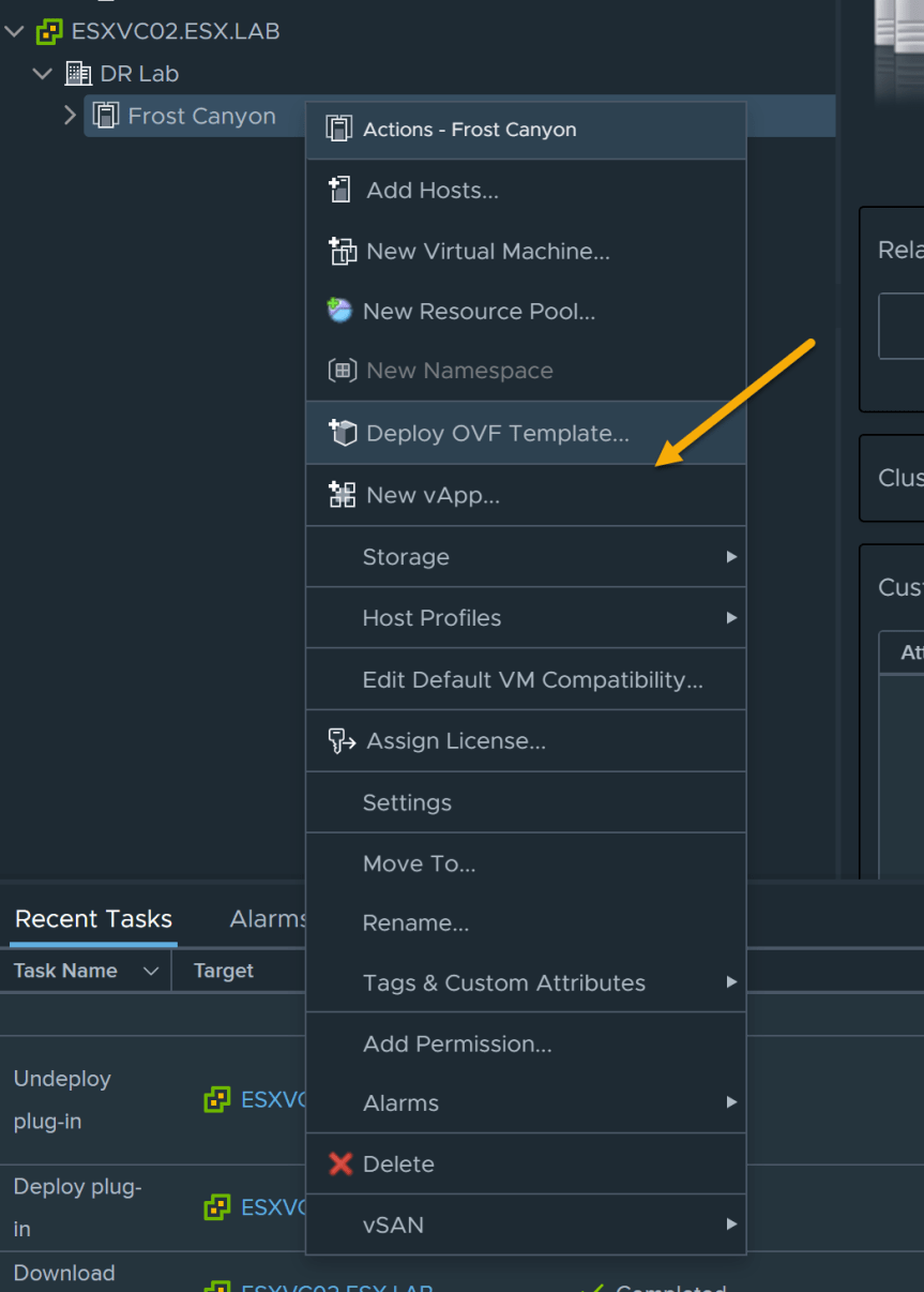
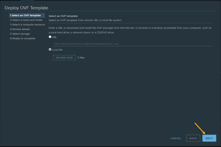
- Log into vCenter and right click on the compute resource and select “Deploy OVF”
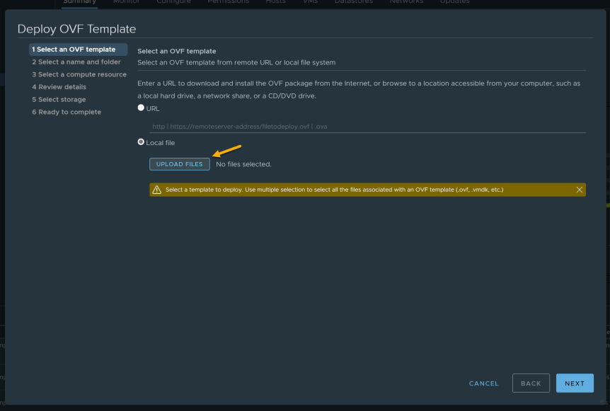
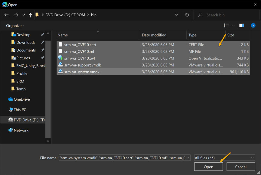
- Select “Local File” and click “Upload Files”. Mount the ISO that was downloaded from VMware. After mounting the ISO, open the folder called “Bin”. Select every file inside the “bin” folder and click “Open”. After the files have been selected, press “Next”
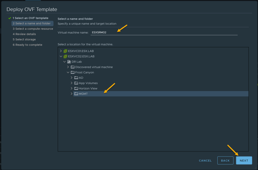
- Next provide a virtual machine name and a folder location for the virtual machine.
In this Demo, I will be calling my virtual machine “ESXSRM02”
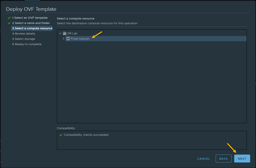
- Select a compute resource
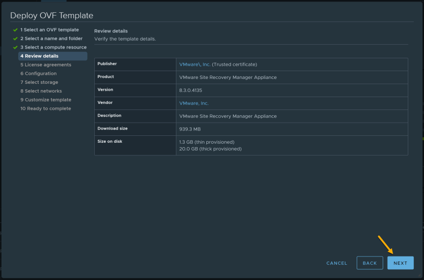
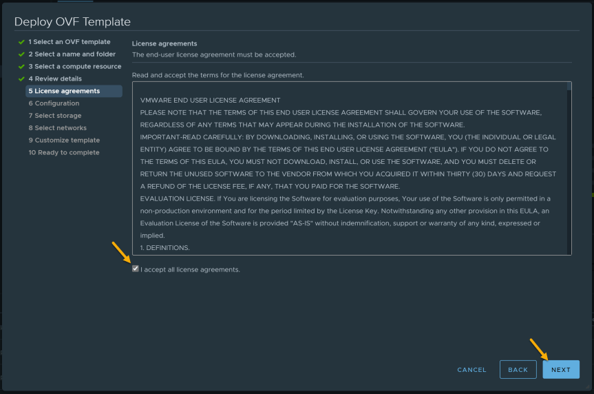
- Review details and accept the EULA
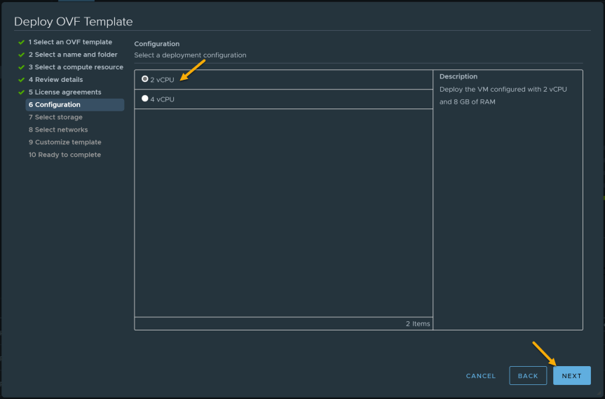
- On the configuration page, select a deployment configuration for your environment. For my home lab deployment, I will be selecting “2vCPU”.
Deployment Type
| Option | Description |
|---|---|
| Light | 2 vCPU, 8 GB RAM, one 16 GB hard disk, and one 4 GB hard disk, 1 Gbit network card. You can use the light deployment type for deployments that protect less than 1000 virtual machines. |
| Standard | 4 vCPU, 12 GB RAM, one 16 GB hard disk, and one 4 GB hard disk, 1 Gbit network card. Use the standard deployment type for deployments that protect more than 1000 virtual machines. |
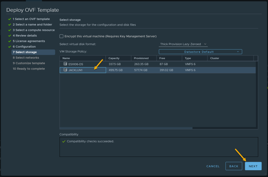
- Select a datastore where the Virtual Appliance will be deploying to.
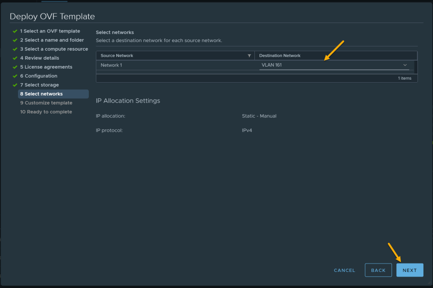
- Select the port group you will be using for this deployment.
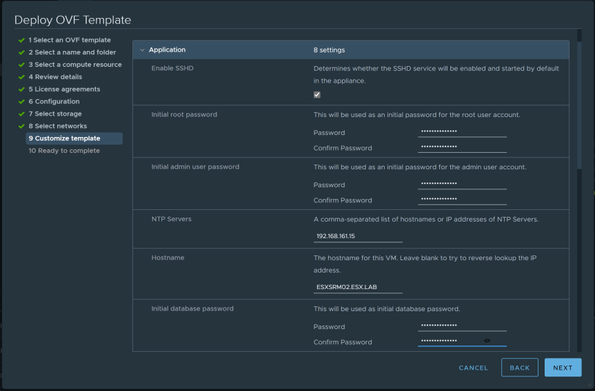
- Customize Template
- Enable SSHD = Enabled
- Set Initial root password
- Set Initial admin password
- NTP Server = FQDN or IP Address
- Hostname = ESXSRM02.ESX.LAB
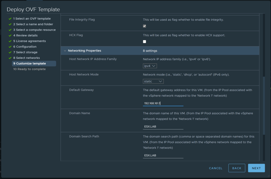
- File Integrity flag = Enabled
- Host Network IP Address Family = IPV4
- Host Network Mode = Static
- Default Gateway = X.X.X.X
- Domain = ESX.LAB
- Domain Search Path = ESX.LAB
- Domain Name Servers = X.X.X.X
- Network 1 IP Address = X.X.X.X
- Network 1 Netprefix = Enter subnet prefix length. (For example 255.255.255.0 = 24)
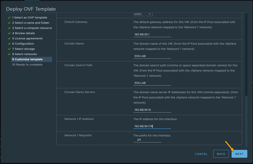
After you have completed the customize template requirements, finish the OVF template. In vCenter, you should see in “Recent Tasks” the Virtual Appliance being deployed.
Note: Make sure both SRM VA have been deployed at the Protected site and Recovery site before you continue.
Configure SRM Virtual Appliance
- After powering on the SRM Virtual Appliance, open a remote console and verify the appliance has fully booted.
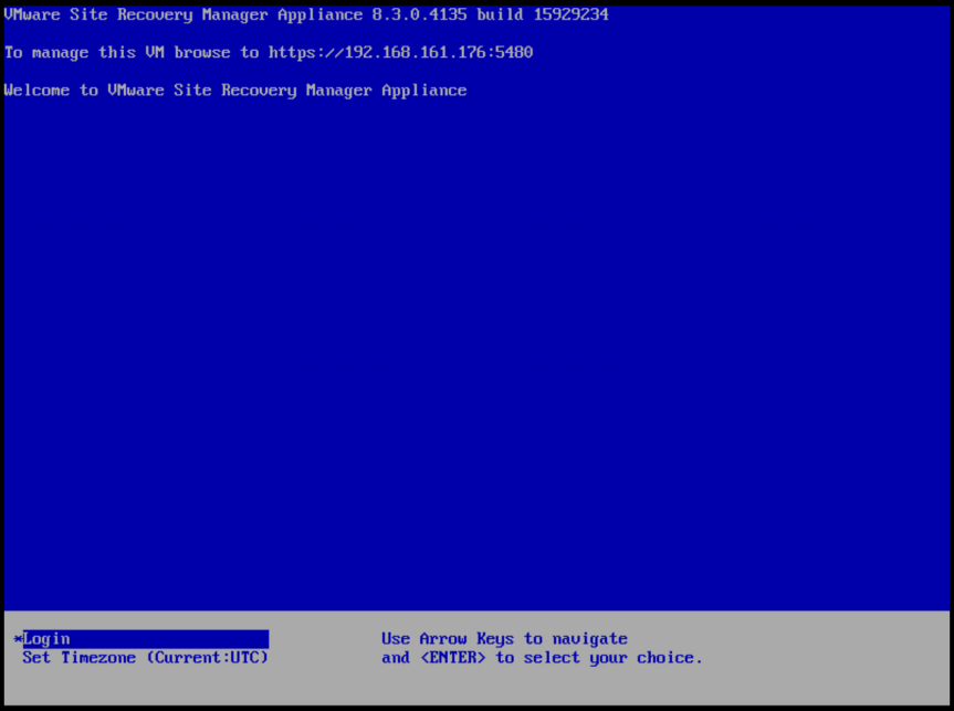
- Open a web browser and go to https://appliance-IP-address-or-FQDN:5480

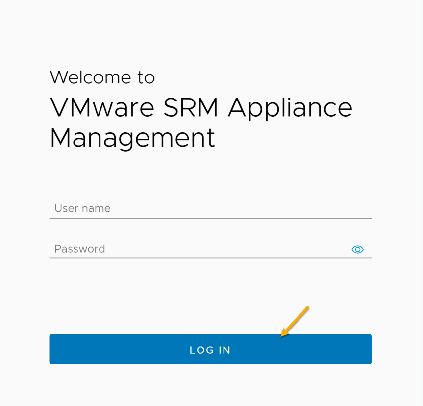
- Log into the VAMI with the “admin” account credentials provided during the OVF deployment.
- Before we start the “configure appliance” process, lets verify Networking, Time, and Syslog Forwarding.

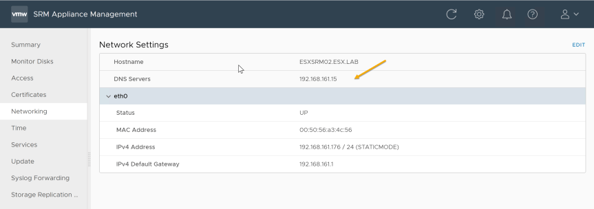
- Select “Networking” tab and verify that DNS servers IP address is configured correctly. If the DNS server is misconfigured, press “Edit” and add the correct DNS servers IP addresses.
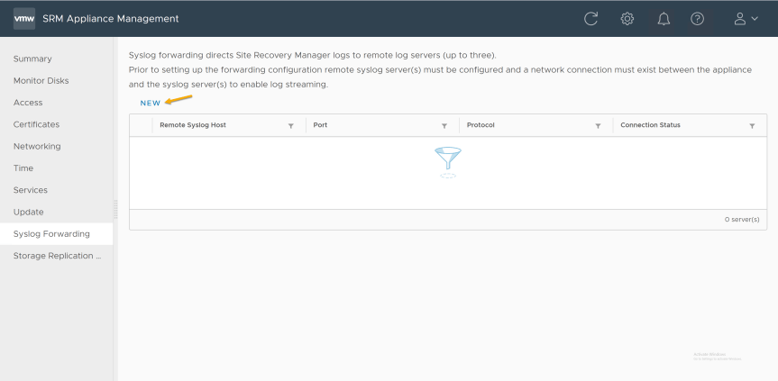
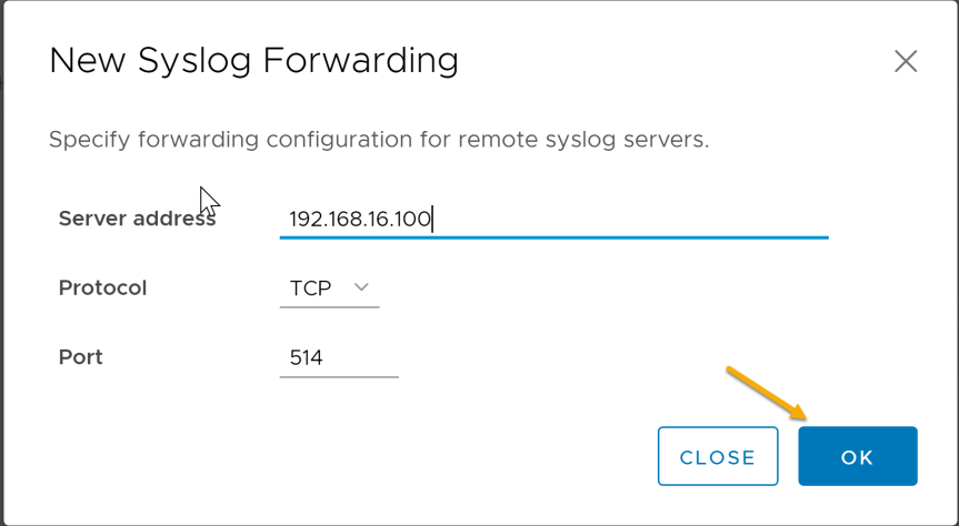
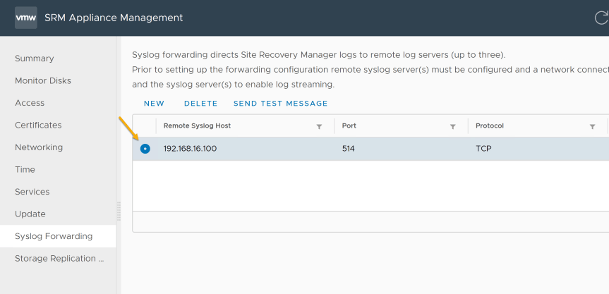
- Select “Syslog Forwarding” tab and press “New”
- Server Address = IP address or FQDN of the syslog server
- Protocol = TCP, UDP, RELP
- Port = 514 (Or syslog port for your environment.)
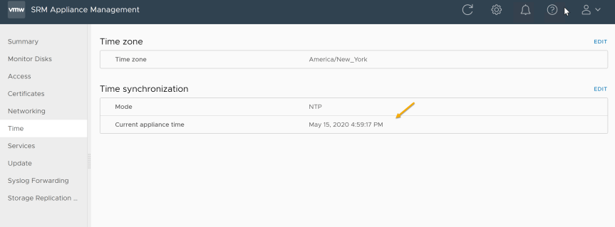
- Select “Time” tab and verify the appliance time is current for your environment.
Note: It is important that time between vCenter and SRM is not skewed. If the time skewed you will receive error during the “Configure Appliance” process.
Note: Make sure both the Protected site and the Recovery site have been configured before you continue.
Connect to vCenter Server
When connecting to vCenter, SRM registers extension to the vCenter Server. This allows SRM to utilize vCenter resources like storage management, guest customization, etc.
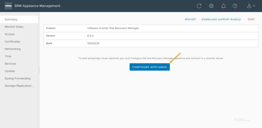
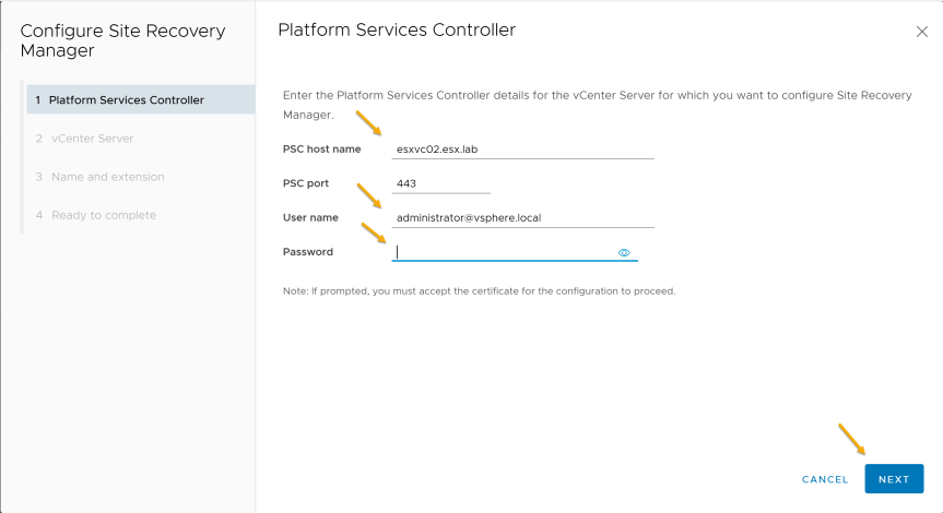
- On the “summary” tab, click on the “Configure Appliance” button.
- On the “Platform services controller” page provide the PSC information that the SRM will be registering with.
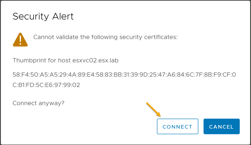
- Press “Connect” on the security alert
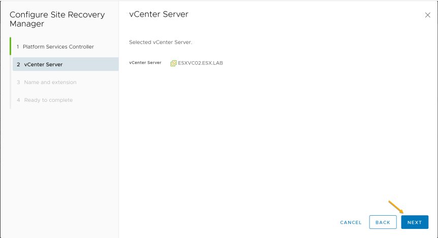
- On the “vCenter Server” page, verify or select the correct vCenter Server.
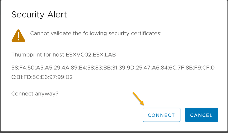
- Press “Connect” on the security alert
- On the “Name and Extension” configure the Site Name, Administrator Email, and Local host.
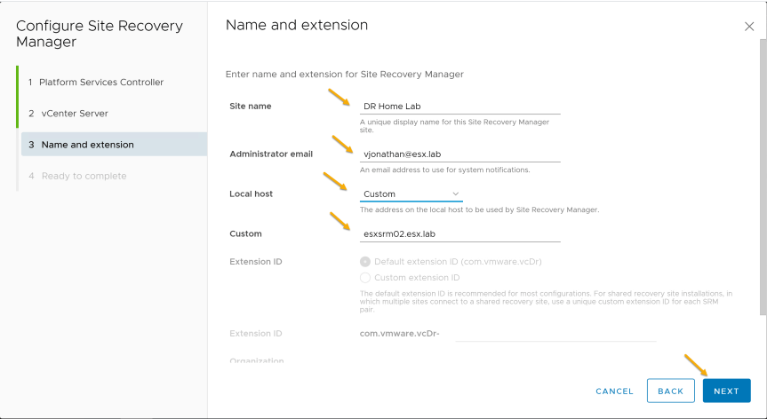
- On the “Ready to complete” page press finish and Site Recovery Manger will start registering with the vCenter server.
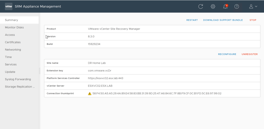
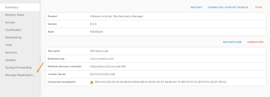
- After successfully configuring Site Recovery Manager, the Summary page should show its registered with a vCenter Server.
Note: Make sure both the Protected site and the Recovery have been connected to vCenter before you continue.
New Site Pair
In SRM, a Site Pair is used to connect the protected and recovery site virtual appliances.
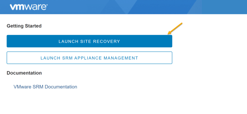
- In a web browser, go to https://appliance-IP-address-or-FQDN of the Site Recovery Manger virtual appliance.

- Click on “Launch Site Recovery”
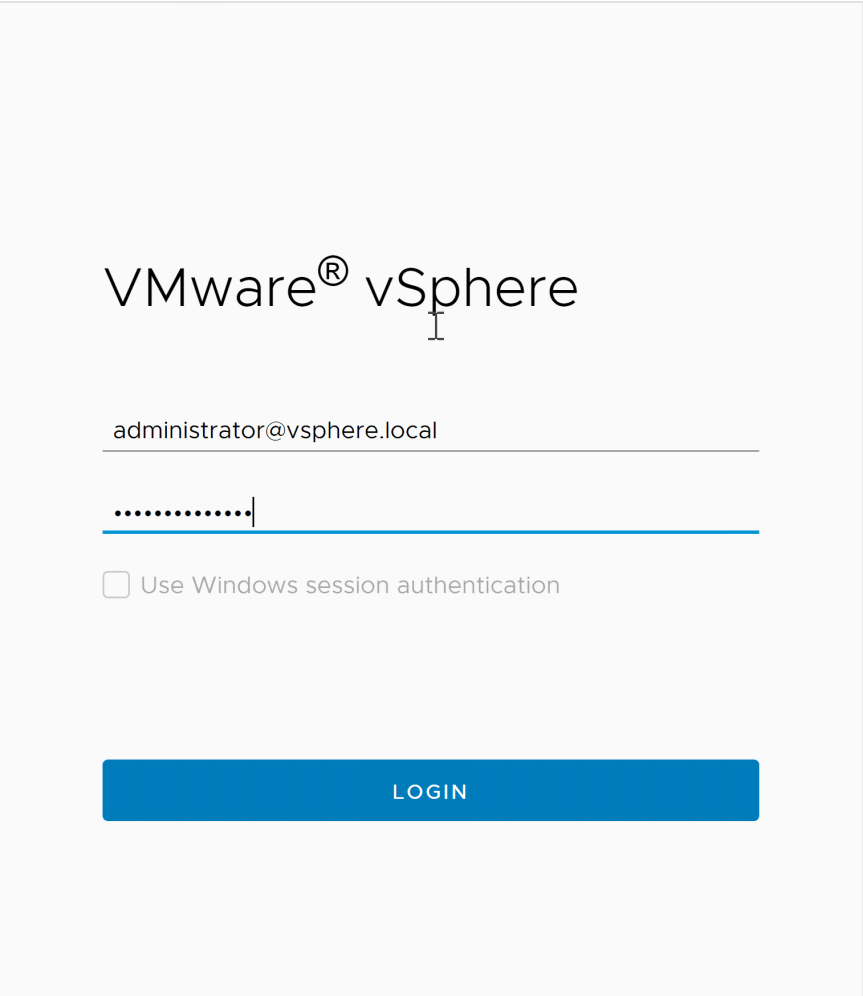
- Login with your vCenter credentials
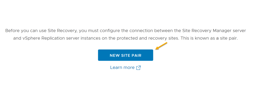
- Click on “New Site Pair”
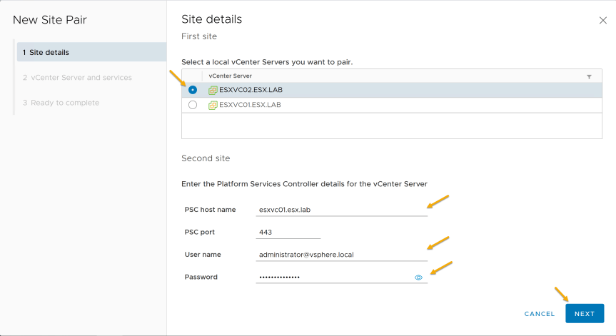
- On “Site Details”, select the local vCenter Server and enter information for the second site.
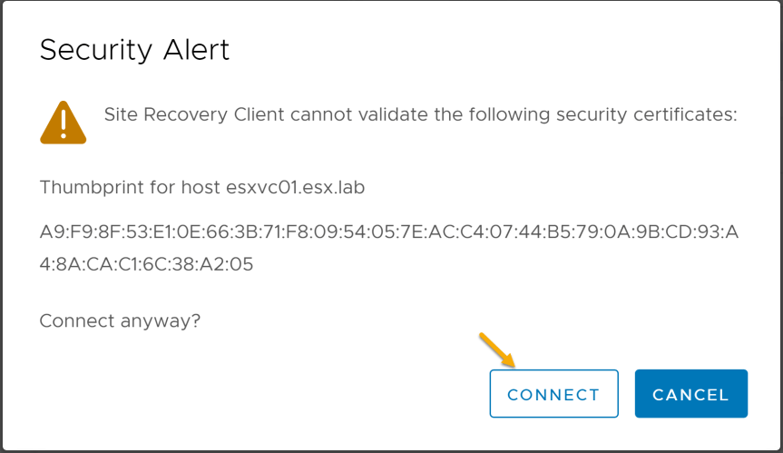
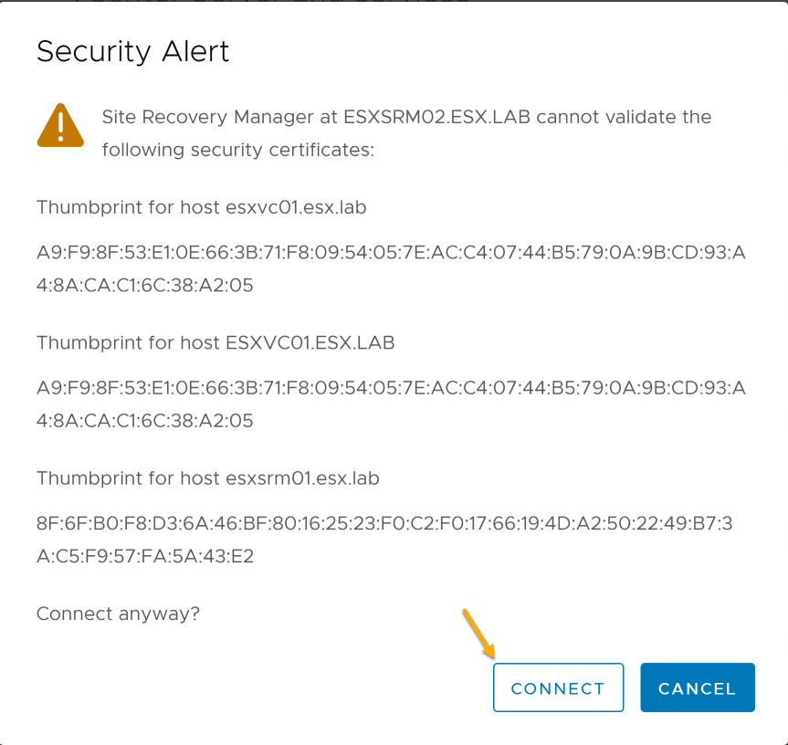
- Press “Connect” on the security alert
- Select the remote vCenter and services on the “vCenter Server and Services”
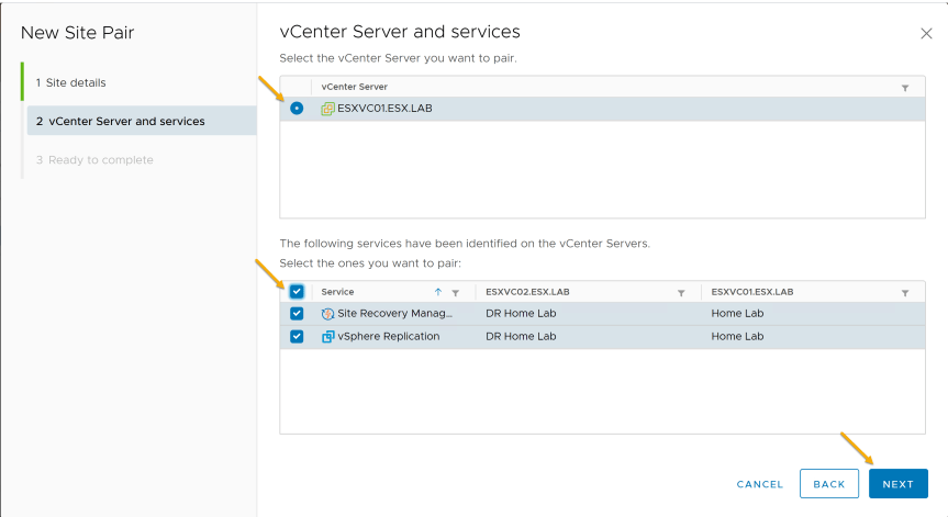
- Press “Connect” on the security alert
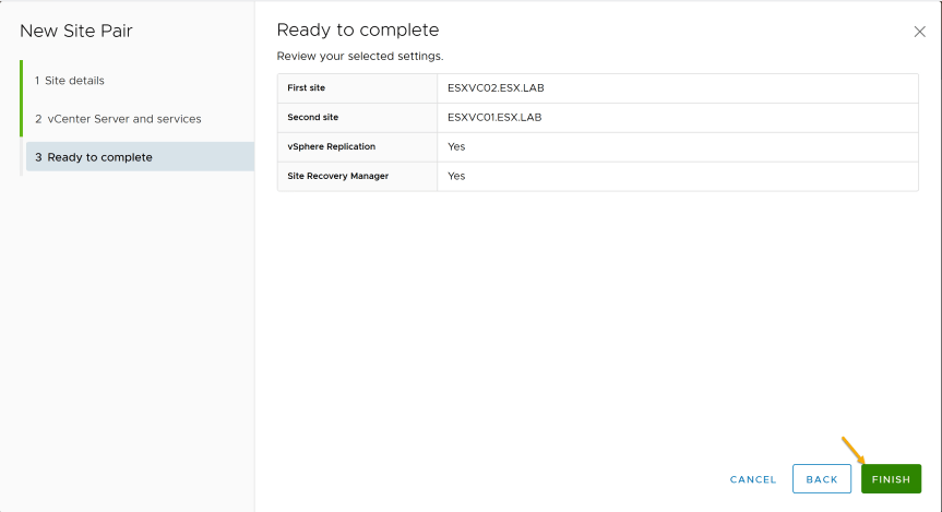
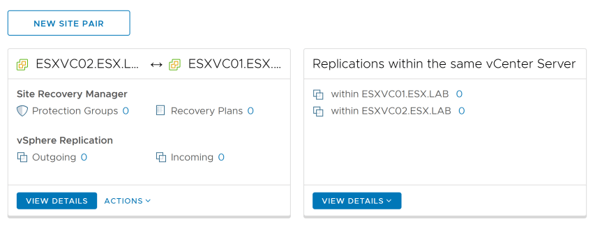
- Press “Finish” on the “Ready to complete” page
- After successfully creating a site pair, Site Recovery Manager
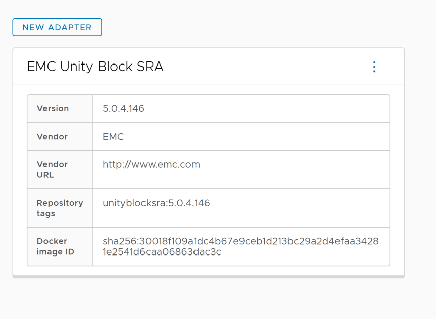
Installing Storage Replication Adapter (SRA)
In SRM, when protecting virtual machines using array-based replication. You will be required to install “Storage Replication Adapter” based on each storage array used.
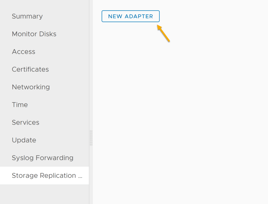
- From the “Summary” page, click on “Storage Replication Adapters”
- Click on “New Adapter”
- Click “Upload”
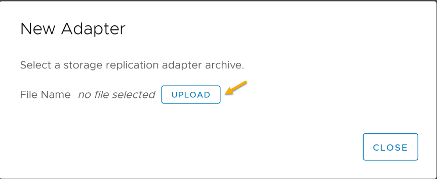
- Select SRA you wish to upload and click “Open”
- The “Storage Replication Adapters” page should now show the adapter has successfully uploaded and installed.
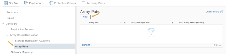
Configure Array Pair
In SRM, after creating a new Site Pair and installing Storage Replication Adapter (SRA). SRM can discover replicated devices, computer datastore, and initiate storage operations.
-
Log into Site Recovery Manager
-
Select “Array Pair” and then press “Add”
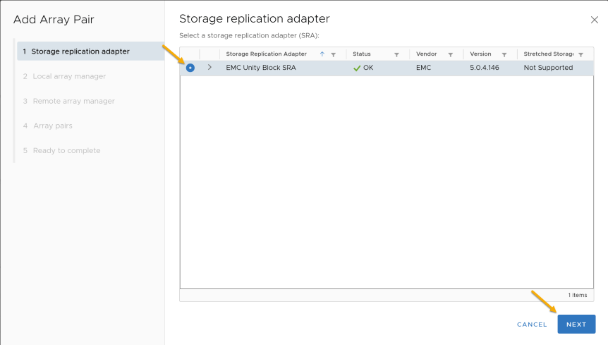
- Select “Storage Replication Adapter (SRA)” from the list and press “Next”
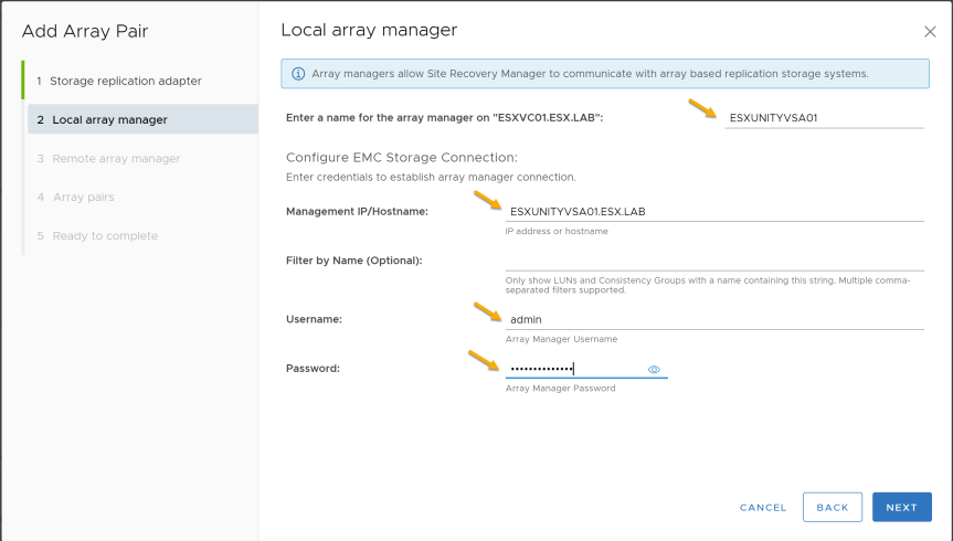
- Configure “Local Array Manager” , press “Next”
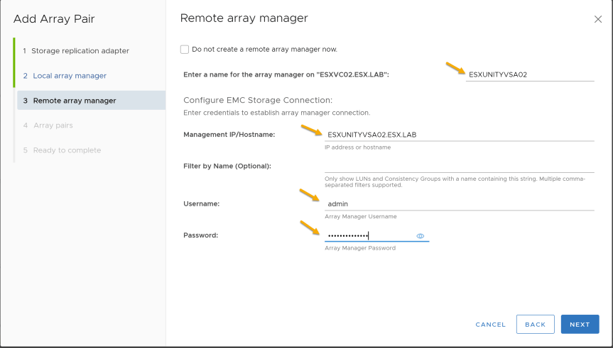
- Configure “Remote Array Manager” , Press “Next”
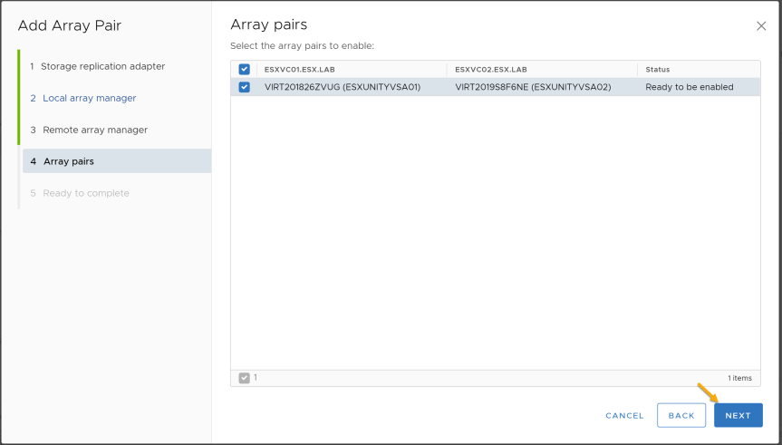
- Verify the “Array Pair” and press “Next”
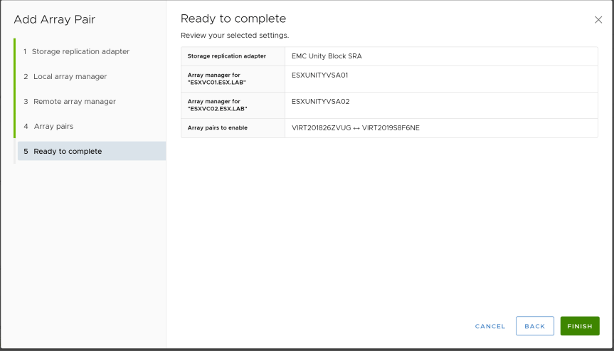
- Press “Finish” to complete “Add Array Pair”
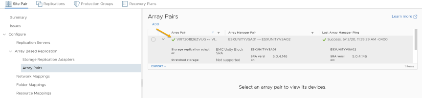
- You should now see the Array Pair configured after completing “Add Array Pair”
Configure Inventory Mappings
In SRM, Inventory Mappings are used to link objects between the protected and recovery site when recovering the protected virtual machines. Inventory mappings will be need to be configured before creating a protection group.
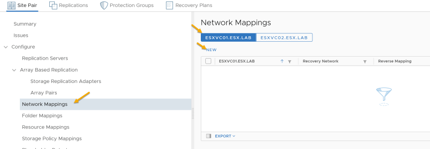
Network Mappings
-
Select “Network Mappings”
-
Select either Protected or Recovery site and press “New”
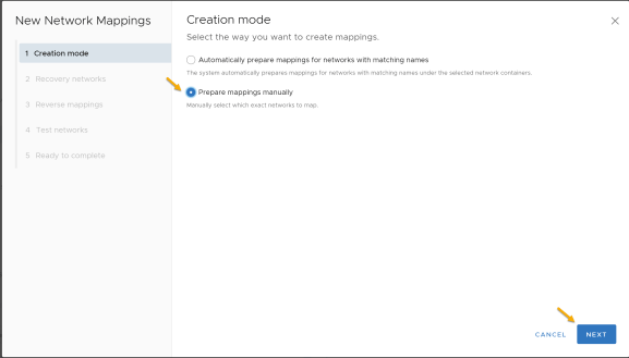
- On the “Creation Mode” you will be given two choices. For this demo, I will be selecting “Manually”.
| Option | Description |
|---|---|
| Automatically | Site Recovery Manager automatically maps networks and folders on the protected site to networks and folders on the recovery site that have the same name. |
| Manually | To map specific networks and folders on the protected site to specific networks, folders, and resources on the recovery site. |
| Reference |
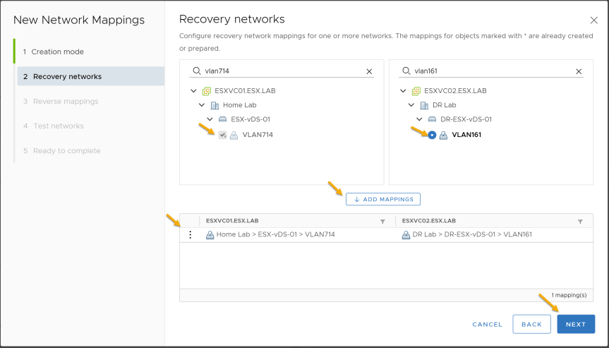
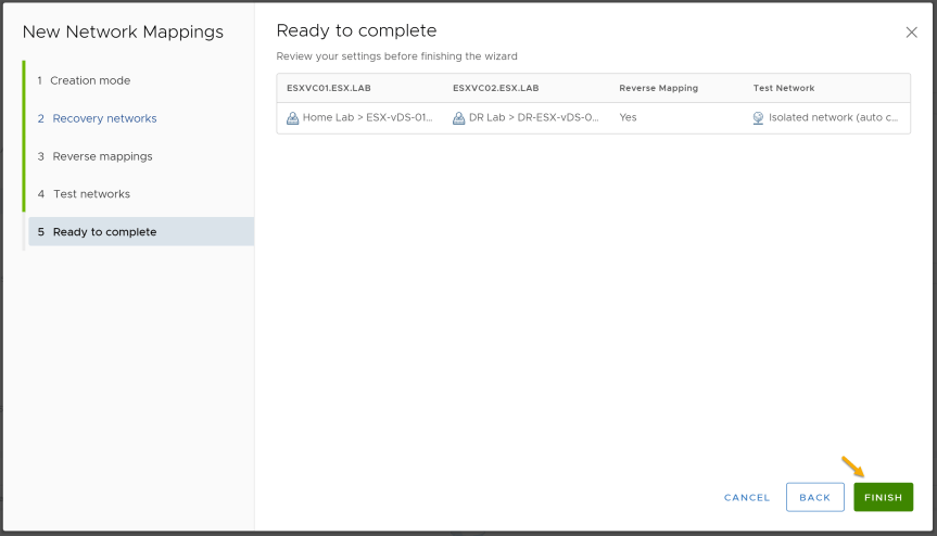
- On the “Recovery Networks” page, select a Port Group at the protected site and then select the corresponding Port group at the Recovery site. Once you have selected both, click on “Add Mappings”. After configuring all of network mappings, press “Next”
- Select the reserve mapping and press “Next”

- On “Test Networks” page, I will be leaving the defaults. Isolated network will be used when testing a recovery plan.
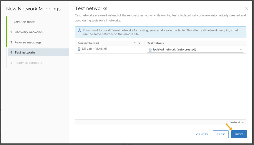
- Press “Finish” to complete adding a network mapping
Adding IP Customization to Existing Network Mapping
In SRM, IP Customization allows SRM to automatically change the network configuration of virtual machine. This functionally can be used for failover and failback.
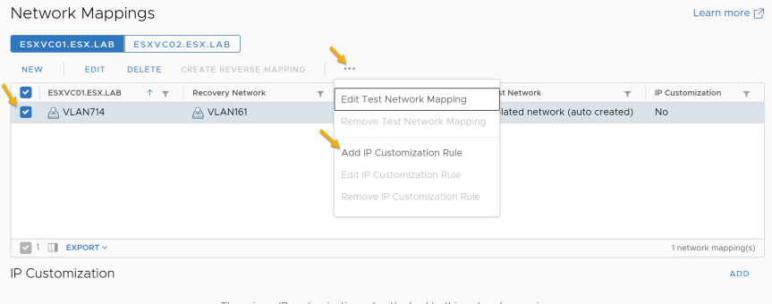
Adding IP Customization at the Protected site Network Mapping
-
On the “Network Mapping” page, select the Protected Site
-
Select existing “Network Mapping” and select “Add IP Customization Rule”.
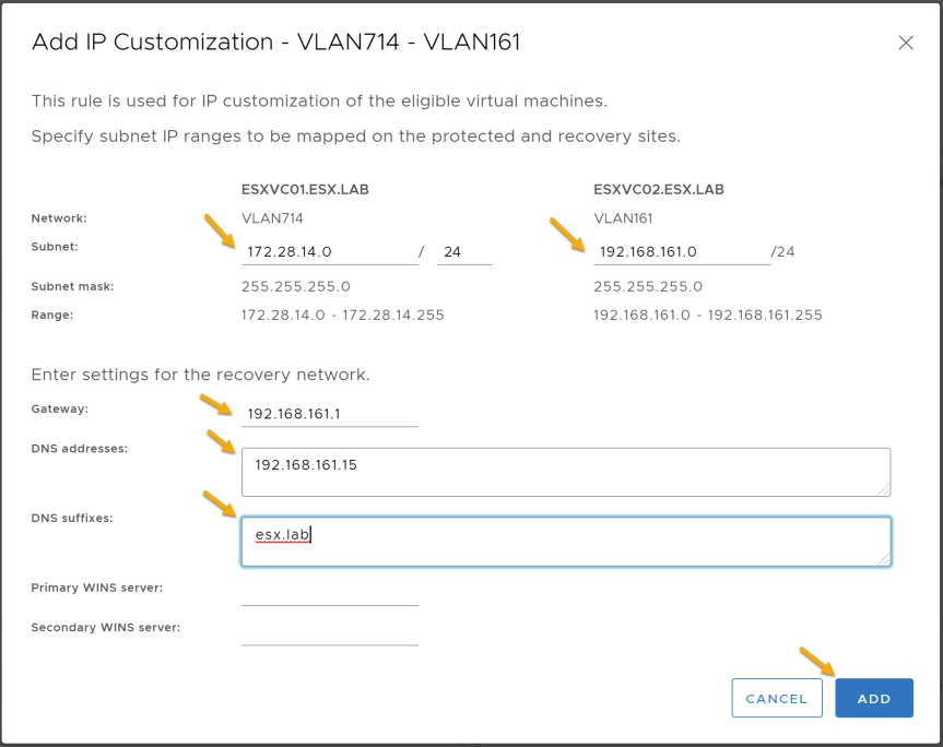
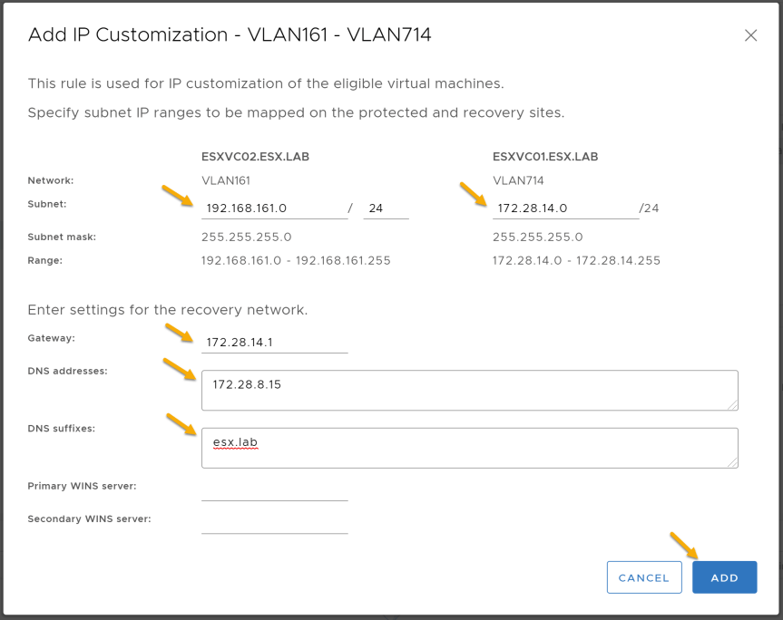
- Configure the subnet information on both the protected and recovery site. After configuring the subnet information, configure the recovery network gateway, DNS addresses, and DNS Suffix. After completing required information, press “Add”
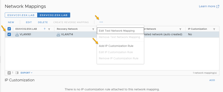
Adding IP Customization at the Recovery Site
-
On the “Network Mapping” page, select the Recovery Site
-
Select existing “Network Mapping” and select “Add IP Customization Rule”
- Configure the subnet information on both the protected and recovery site. After configuring the subnet information, configure the recovery network gateway, DNS addresses, and DNS Suffix. After completing the required information, press “Add”
Folder Mappings
-
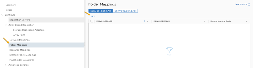
Select “Folder Mappings”
-
Select either Protected or Recovery site and press “New”
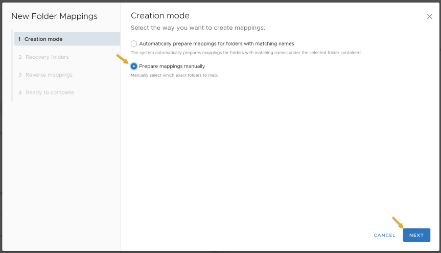
- On the “Creation Mode” you will be given two choices. For this demo, I will be selecting “Manually”.
| Option | Description |
|---|---|
| Automatically | Site Recovery Manager automatically maps networks and folders on the protected site to networks and folders on the recovery site that have the same name. |
| Manually | To map specific networks and folders on the protected site to specific networks, folders, and resources on the recovery site. |
| Reference |
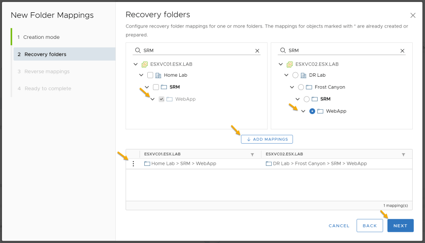
- On the “Recovery Folders” page, select a folder at the protected the site and then select the corresponding folder at the Recovery site. Once you have selected both, click on “Add Mappings”. After configuring all of the folder mappings, press “Next”
- Select the reverse mapping and press “Next”
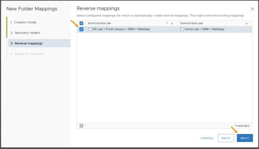
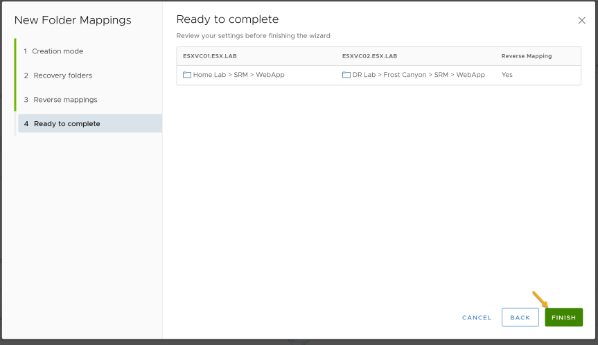
- Press “Finish” to complete adding a folder mapping.
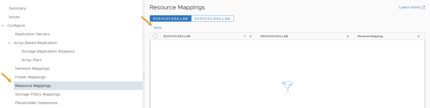
Resource Mappings
-
Select “Resource Mappings”
-
Select either Protected or Recovery site and press “New"
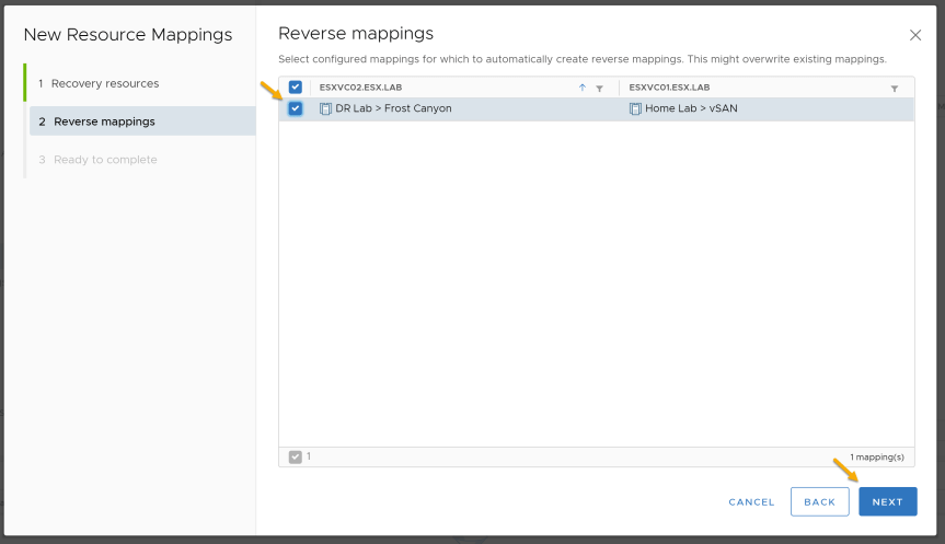
- On the “Recovery Resources” page, Select a cluster at the protected site and then select the corresponding cluster at the Recovery site. Once you have selected both click on “Add Mappings”. After configuring all of resource mappings, press “Next”
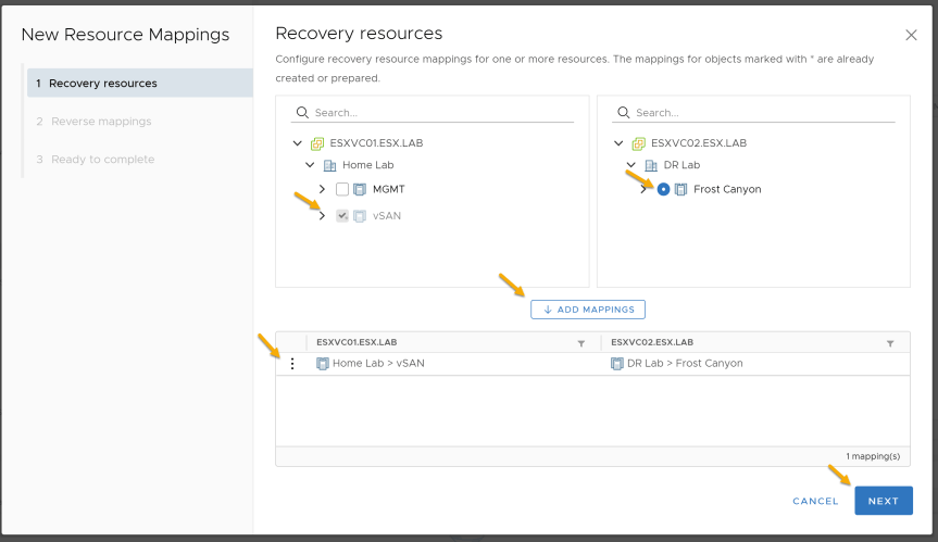
- Select the reverse mapping and press “Next”
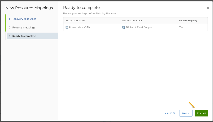
- Press “Finish” to complete adding a resource mapping.
Placeholder Datastores
In SRM, a placeholder datastore is used to store the placeholder virtual machines.
-
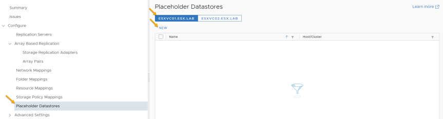
Select “Placeholder Datastore”
-
Select the Protected Site and press “New”
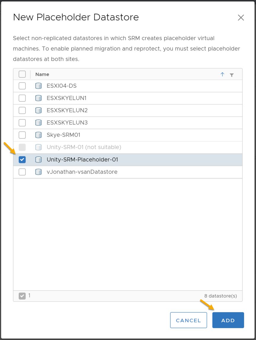
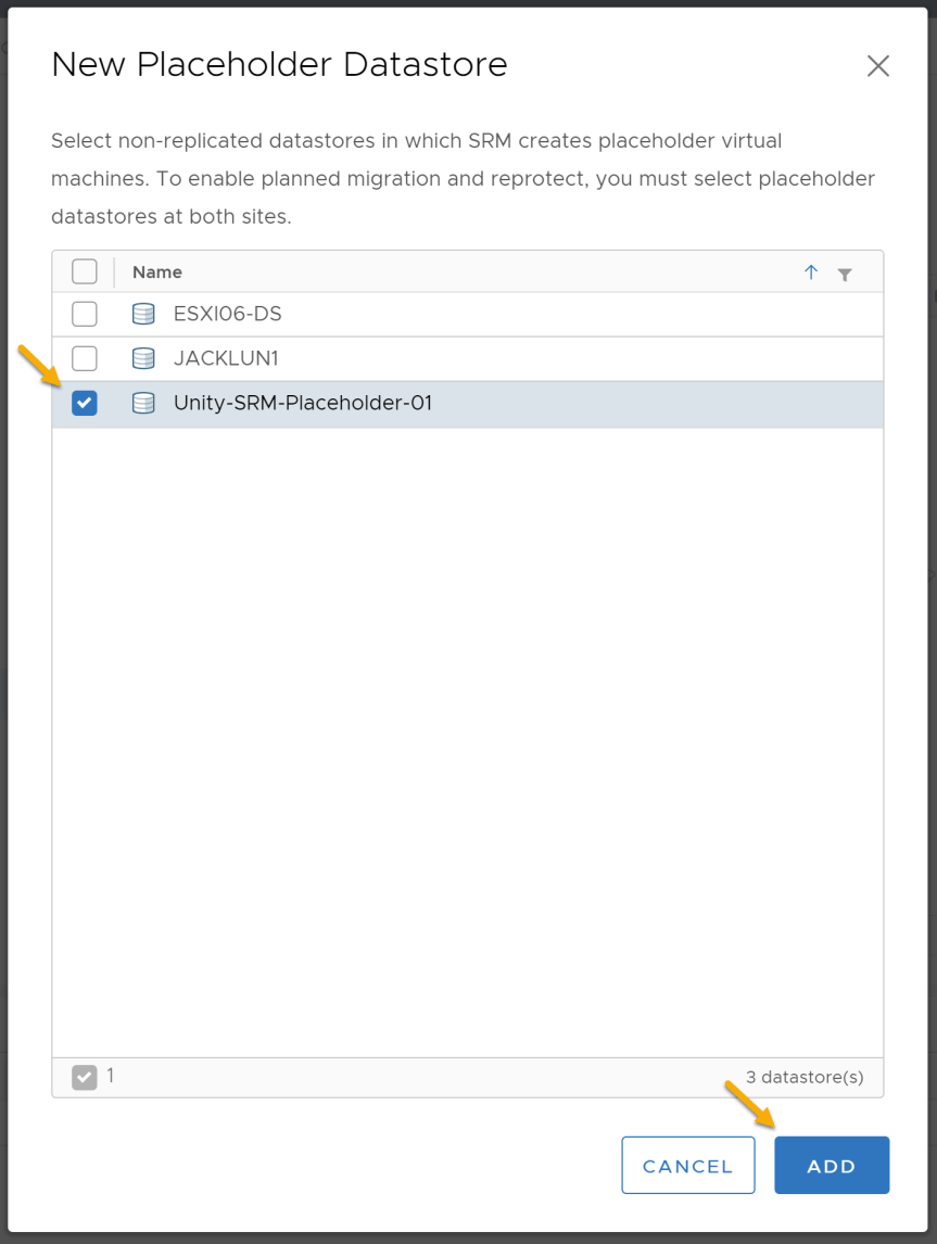
- Select the non-replicated datastore that would like to store the placeholder for the protected virtual machines. Press “Add” to complete adding a placeholder datastore at the protected site.
- Select the Recovery Site and press “New”
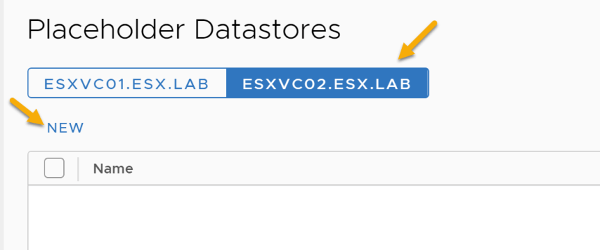
- Select the non-replicated datastore that would like to store the placeholder for the protected virtual machines. Press “Add” to complete adding a placeholder datastore at the recovery site.
Creating Protection Group and Recovery Plan
In SRM a Protection Group allows you group VMs together that you intend to recover together. A Protection Group allows you to protect VMs based on either array based replication or vSphere Replication. After creating a Protection Group, a Recovery Plan is used to execute a sequence of steps that controls the recovery process of the protected virtual machines.
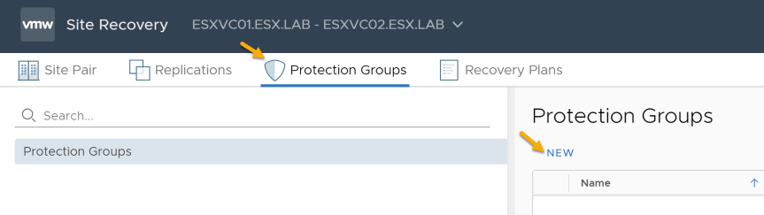
- Select “Protection Groups” and Press “New”
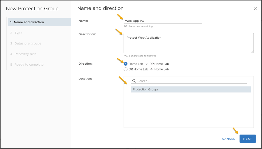
- Configure the name, description, direction, and location on the “Name and Direction”. Once completed press “Next”
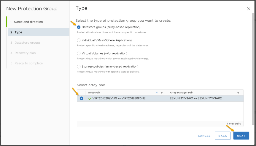
- Select the type of protection group you want to create. For this demo, I will be selecting “Create array-based replication protection group”
| Option | Action |
|---|---|
| Create an array-based replication protection group | Select Datastore groups (array-based replication) and select an array pair. |
| Create a vSphere Replication protection group | Select Individual VMs (vSphere Replication). |
| Create a Virtual Volumes (vVol replication) protection group | Select Create a Virtual Volumes (vVol replication) |
| Create a storage policy protection group | Select Storage Policies (array-based replication). |
| Reference |
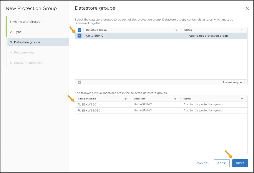
- Select the datastore that is currently being replicated. Once selected, if a Virtual Machine is currently residing on that datastore Site Recovery Manager will add it the protection group.
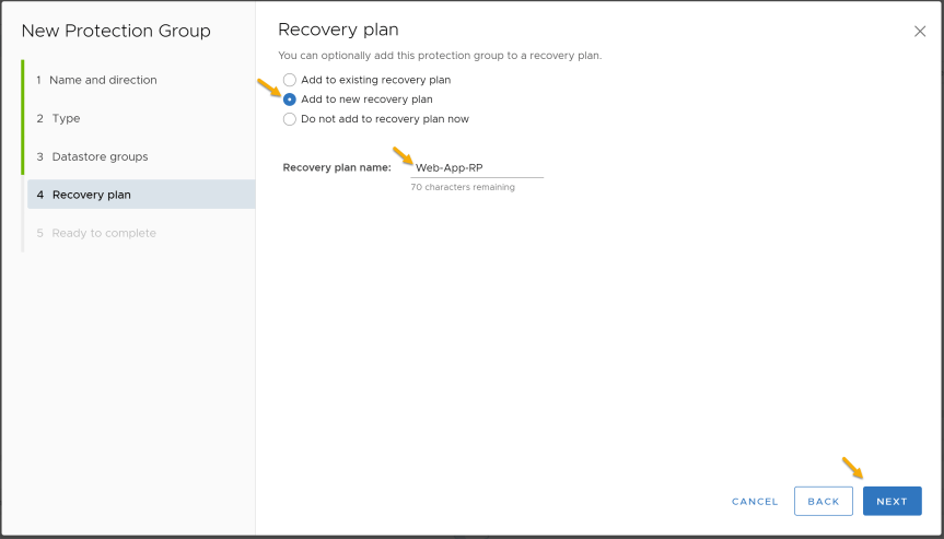
- You can configure a new recovery plan or add the protection group to another recovery plan. In this demo, I will be selecting “add to a new recovery plan” and configuring the recovery plan name.
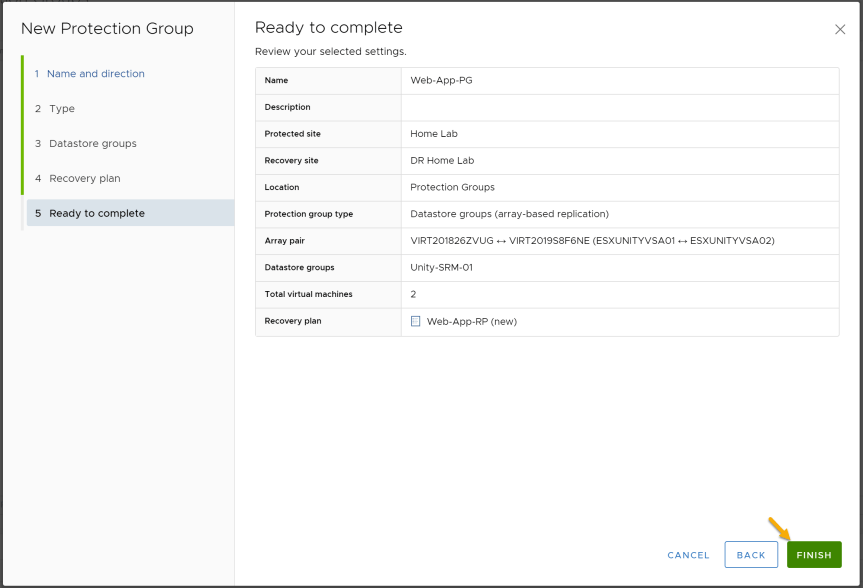
- Press “Finish” and verify the Protection Group was created.
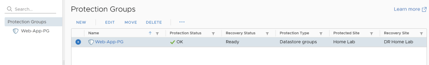
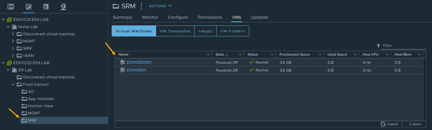
- In vCenter you should we should see the placeholders created at the recovery site.
Configure Recovery Plan
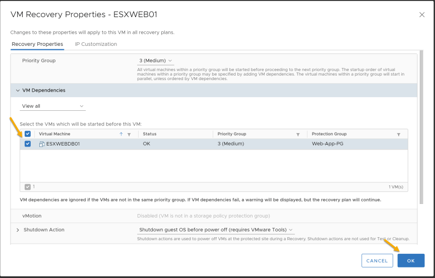
In SRM, a Recovery Plan has a couple of different Virtual Machine recovery settings. The Recovery settings included changing the priority group, pre and post power on steps, configure VM dependencies, shutdown action, and startup action.
More info can be found here.
Virtual Machine Recovery Settings
-
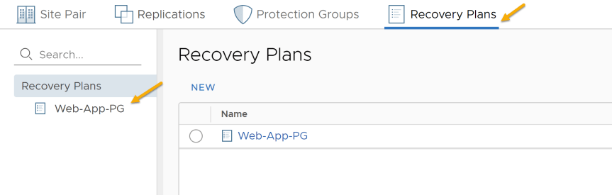
Select “Recovery Plans”
-
Select the “Recovery Plan” you want to configure
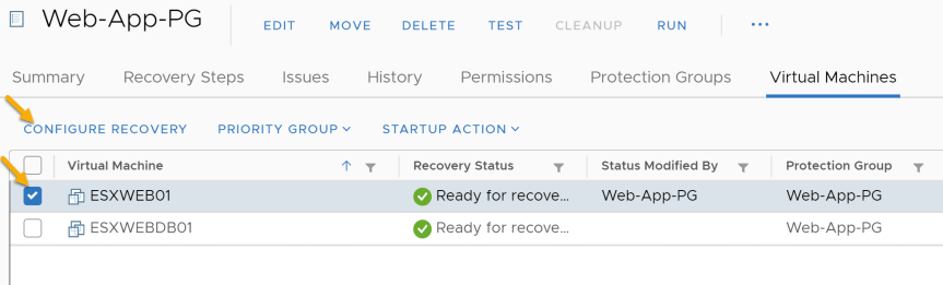
- Select the “Virtual Machines” tab

- Select a Virtual Machine you want to configure and press “Configure Recovery”. For this demo, I will select “ESXWEB01” and configure “VM Dependencies” to depend on “ESXWEBDB01”. This means “ESXWEB01” will depend on “ESXWEBDB01” before powering on.
Test a Recovery Plan
In SRM, when testing a recovery plan. This will allow you to verify your recovery plan steps have been configured correctly without disrupting production.
-
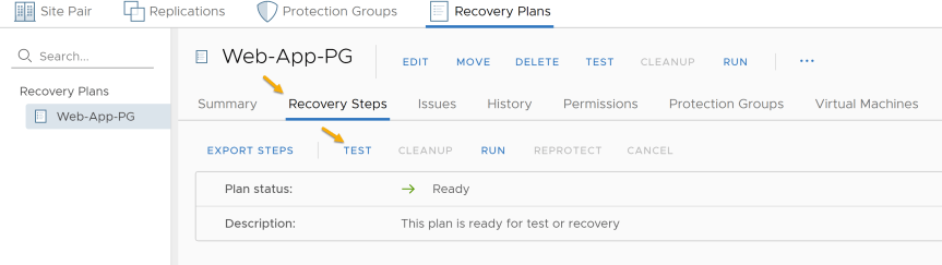
Select “Recovery Plans”
-
Select the “Recovery Plan” you want to test.
- Select the “Recovery Steps” tab and select “Test”
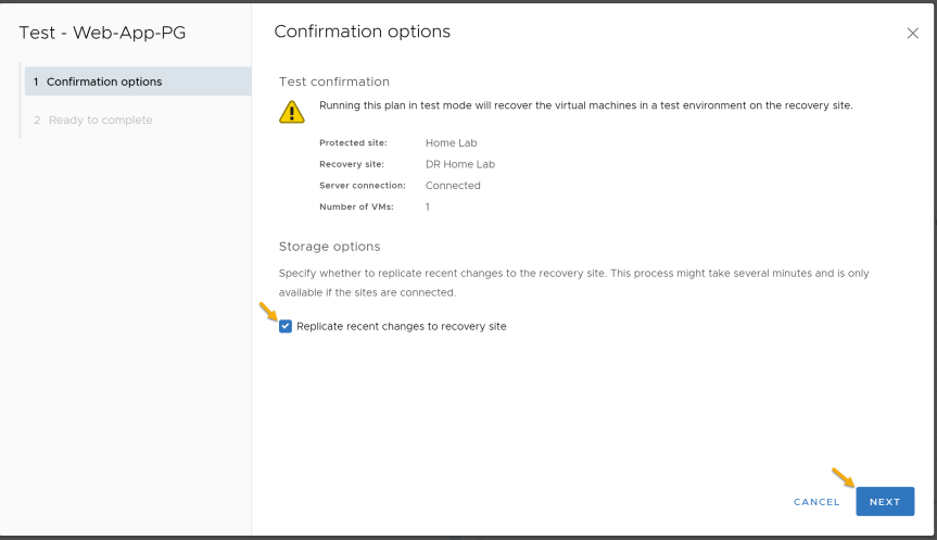
- Verify “Replicate recent changes to recovery site” is selected and press “Next”
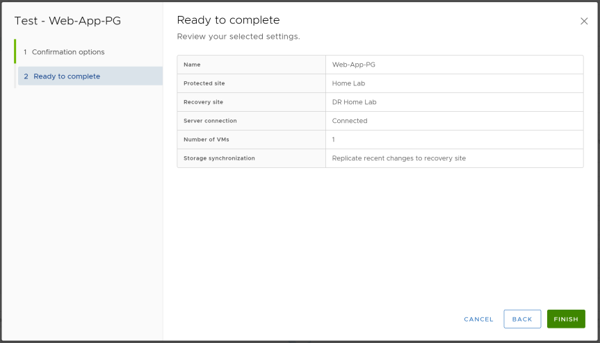
- Press “Finish” to start testing the recovery plan
- On the “Recovery Steps” tab, you will be able to watch the recovery steps in real time. This page will help with troubleshooting the recovery plan by displaying errors and warnings.
- After recovery plan test has completed, Troubleshoot any warnings or errors in the recovery plan. Press “Cleanup” once you’re done troubleshooting.
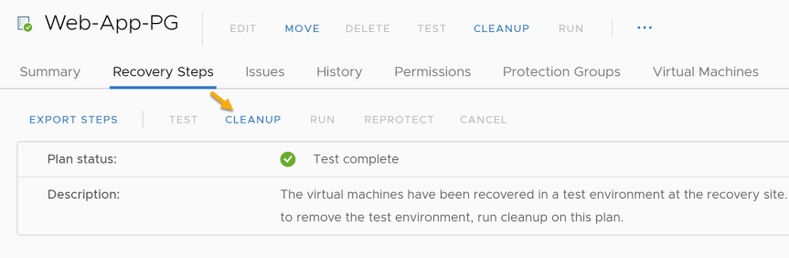
- After the “Cleanup” has completed, you have successfully tested a recovery plan.
Run a Recovery Plan
When running a recovery plan this action will attempt to shutdown the VMs at the protected site and turn on the VMs at the recovery site. As a friend once told me, he calls this button “I hope you have resume up to date”.
-
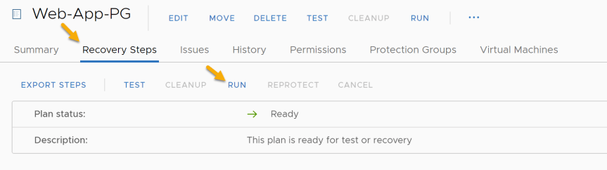
Select “Recovery Plans”
-
Select the “Recovery Plan” you want to run.
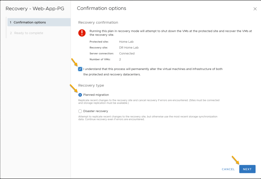
-
First we need to select the checkbox “I understand that this process will permanently alter the virtual machines and infrastructure of both the protected and recovery datacenters.”
-
Select between the following “Recovery Types”
| Planned migration | Replicate recent changes to the recovery site and cancel recovery if errors are encountered. (Sites must be connected and storage replication must be available.) |
|---|---|
| Disaster recovery | Attempt to replicate recent changes to the recovery site, but otherwise use the most recent storage synchronization data. Continue recovery even if errors are encountered. |
For this demo, I will be selecting “Planned Migration” since my protected site and recovery site are still connected. Press “next” to continue.
- Press “Finish” to run the recovery plan
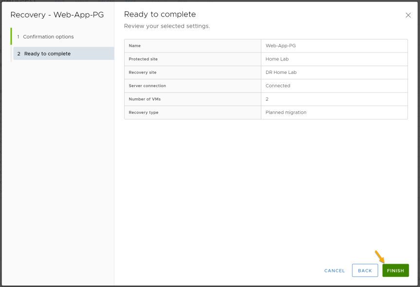
- On the “Recovery Steps” tab, you will be able to watch the recovery steps in real time. This page will help with troubleshooting the recovery plan by displaying errors and warnings. Within vCenter you should now see the protected site VMs are now placeholders and the recovery site VMs are now powered on.
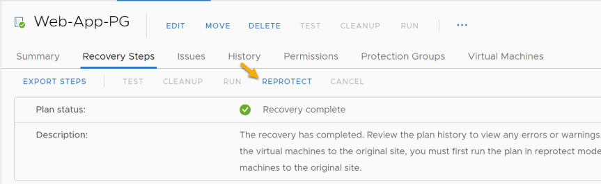
- After recovery plan has ran successfully, we will now need to reprotect the recovery plan.
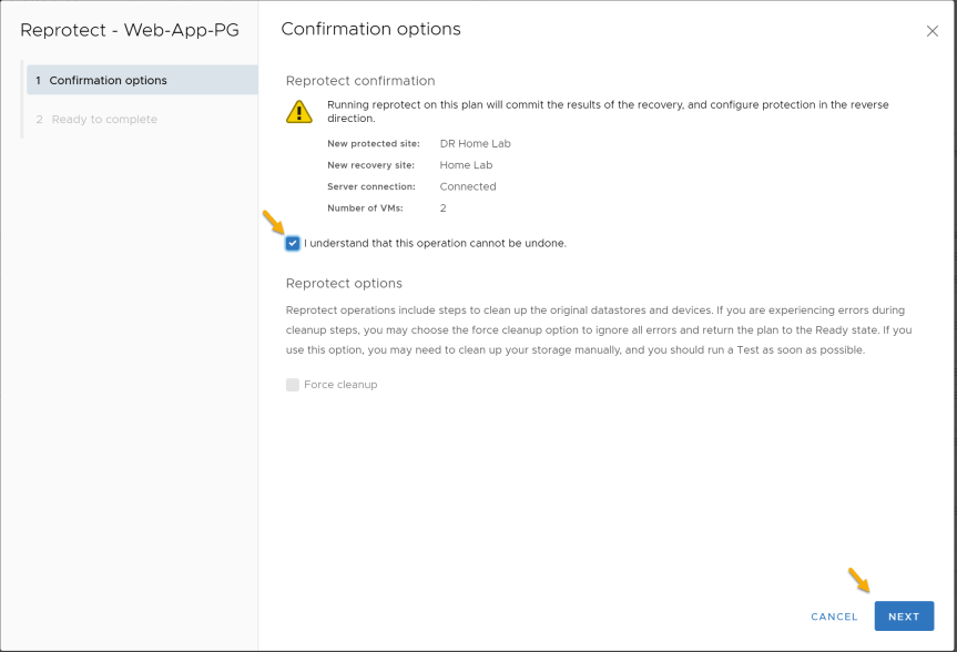
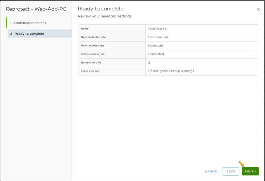
- First we need to select the checkbox “I understand that this operation cannot be undone.”
Note: The reason why “Force Cleanup” is greyed out is because the recovery plan ran successfully without any errors. If any errors would have presented itself during the recovery. “Force Cleanup” would be available.
Press “Next” to continue
- Press “Finish” to reprotect the recovery plan
- On the “Recovery Steps” tab, you will be able to watch the reprotect steps in real time.
- After the “Reprotect” has completed, you have successfully ran a recovery plan.